Rover Power Distribution PCB
More power, better thermals, and a fuse that tells you it has blown.
| Where | UCSD Yonder Dynamics |
|---|---|
| When | 2025 |
| Tools | Altium Designer |
| Spec | 24 V / 60 A, two layers |
| Outcome | 20% smaller footprint; deployed on our competition rover |
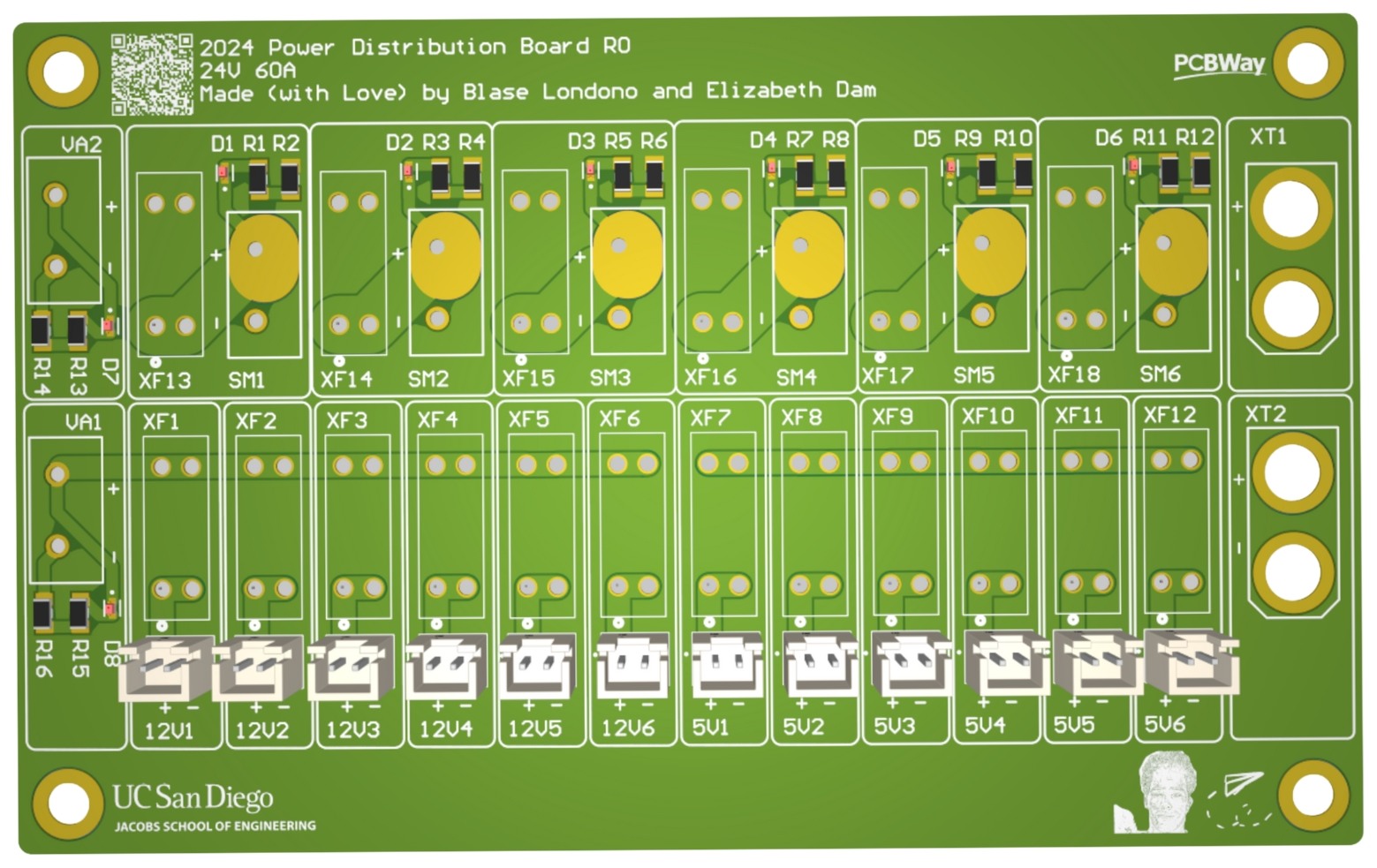
Our rover’s power distribution board needed a connector refresh (JSTs are pretty hard for us to crimp), so while we were at it we took the opportunity to fix a couple of things that had been bothering us.
I rebuilt this board as a custom two-layer schematic and layout in Altium, rerouting around our new Anderson connectors and cleaning up the layout a bit. For thermal headroom under worst-case load and environmental conditions, I used polygon pours around the XF vias and scaled trace widths to each channel’s current draw. I also wired an indicator LED in parallel with every fuse.
I populated and soldered the board when it arrived and ran an electrical stress test on the traces; it handled around 860 W before they burned out. The redesign cut the PCB footprint by 20% and was deployed on last year’s competition rover.